
With Emphasis on SpinLaunch
William M. Gutman
Introduction
Kinetic space launch refers to a launch in which the vehicle is imparted very high initial velocity and leaves the launch apparatus at maximum speed. The vehicle, at least initially, is a simple projectile.
The highest velocity occurs at exit where atmospheric pressure is highest. Therefore
-
-
- The dynamic pressure on the vehicle is highest.
- Atmospheric drag is highest.
- Aero-thermal effects are highest.
-
Currently, no one pursuing kinetic launch systems expects to reach orbit directly with a kinetic system. Rather, a second stage rocket will be used to attain the final increment of orbital speed. Companies do, however, expect to exceed the Karman Line. The Karman Line is the most commonly used definition of the threshold of space. It is 100 km above sea level, which is the approximate altitude at which the speed necessary for an aircraft to maintain aerodynamic flight equals orbital speed. Payloads almost certainly will require the protection of an aeroshell.
Kinetic launch systems include the following:
-
-
- Conventional gun launch. The system is essentially a cannon. The vehicle is accelerated through a tube by the rapidly expanding gases resulting from the combustion of a propellant. The projectile forms a reasonably tight seal with the launch tube (barrel).
- Light gas gun. The system is essentially an air rifle.The vehicle is accelerated through a tube by a working gas that is compressed and then allowed to expand into the acceleration tube. Again, the projectile forms a reasonably tight seal with the launch tube.
- Ram accelerator. The system is essentially a ramjet engine. The vehicle fits loosely within a tube that is filled with a combustable gas mixture. As the vehicle moves through the tube, the gas mixture is locally compressed and combusts behind the projectile, which accelerates on the resulting pressure wave.
- Rail gun. The system is essentially a linear induction electric motor. Electric currents induced in the projectile by a series of coils, and interaction between the induced electromagnetic field and the field from stationary coils cause the vehicle to accelerate through the apparatus.
- Centrifugal accelerator. The system is a giant centrifuge in which a vehicle is constrained by a tether to follow a circular path until is is released and follows a tangential path.
-
System Specific Considerations
Gun Launch
The German Paris guns of the WW I era achieved muzzle velocities of approximately 1600 m/s (5300 ft/s, 3600 mi/hr), 120 km range, and apogee of about 40 km. Gerald Bull and Project HARP achieved 3,048 m/s (10,000 ft/s, 6,818 mi/hr) muzzle velocity and apogee of nearly 170 km. Unfortunately, Bull sold his services to Iraq and was assassinated.
Some of the issues that must be overcome are:
-
-
-
-
- High exit speed requires long, very heavy barrels
- Supplemental propellant charges may be required along the barrel
- It can be difficult to alter pointing of the gun for different trajectories
- Very high speeds cause rapid barrel erosion
-
-
-
Light Gas Gun
“Light gas” refers to the density of the driver gas. Performance improves with increasing acoustic propagation speed, so low molecular weight gases provide better performance. Light gas guns have demonstrated exit speeds up to 8.5 km/s (28,000 ft/s, 19,000 mi/hr, which is greater than orbital speed). The primary application of light gas guns has been to research high speed impacts such as micrometeoroid impacts on space vehicles using low mass, small diameter projectiles. One such gun is located at NASA WSTF east of Las cruces. Concepts for space launch application with larger projectiles have been and are being explored. Many of the issues relating to operating a light gas gun are similar to those associated with a conventional gun. Typically, an explosively driven piston is used to compress the working gas.
Ram Accelerator
A ram accelerator resembles a conventional gun. A projectile moving through a combustible gas mixture in a tube compresses the gas. The gas mixture ignites behind the projectile, which accelerates as it rides the pressure wave. This is very similar to the operation of a ram jet engine. Compared with a true gun, the tube would be much longer, but accelerations are correspondingly smaller. Perhaps surprisingly, accelerators are currently in use for enhancing tunneling and drilling. “Dumb” projectiles (typically concrete castings) are accelerated downward or horizontally for high speed impact at the point of drilling.
Some of the issues that must be overcome are:
-
-
-
-
- A means must be provided to inject the gas mixture into the tube.
- For optimum performance, gas mixture should vary along the tube.
- Projectiles must be placed at the bottom of the tube.
- Projectiles must be imparted sufficient velocity to initiate ram jet operation.
- For tunneling and drilling, tube can be breech loaded.
- For space launch, it’s hard to see how muzzle loading can be avoided.
- A means is required for initial acceleration to achieve ram ignition.
- Typically, tube would be recessed into the ground—think well casing
- Repointing not feasible.
- A separate tube likely would be required for each desired trajectory.
-
-
-
Rail Gun
A rail gun is essentially a linear induction motor. Research by the US Navy demonstrated exit velocities comparable to conventional guns. For space launch applications, very long “barrels” would be required, but are thought to be feasible. Also, very large electric currents would be required. Energy requirements would be measured in MJ released over times measured in ms. Very precise current control would be required, and the support structure (“barrel”) would need to be very strong, but would have to be constructed of non-conductive, non-magnetic materials.
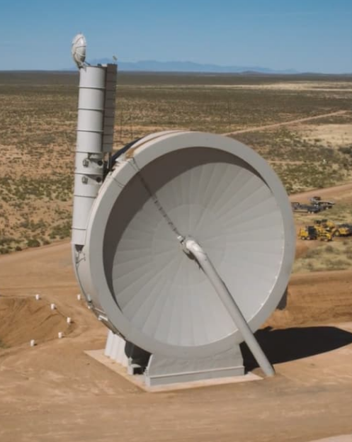
Centrifugal Accelerator
SpinLaunch, a Spaceport America tenant, has explored this concept for several years. The current state-of-the-art is their 33-m diameter centrifuge.
Required accelerations can reach tens of thousands of Gs. These G-levels actually are fairly easy to harden payloads against. By the end of WWII, the Allies were using antiaircraft and artillery shells with vacuum tube electronic proximity fuzes which survived linear and centripetal accelerations on the order of 40 kG.
Some of the issues that must be overcome are:
-
-
-
-
- The vehicle is continuously subjected to centripetal acceleration from spin up to release. Accelerations in the tens of thousands of Gs are required.
- The tether requires very high tensile strength.
- High tangential speeds with acceptable aero-thermal heating levels can only be achieved in a reasonably hard vacuum. Consequently, there must be some type of seal between the atmosphere and the chamber through which the vehicle must pass.
- Inrushing air after release must be dealt with.
- To avoid destroying the internal mechanism on every shot, there must be a counter weight that is released simultaneously with the payload.
- The release mechanism must have very precise timing.
- The plane of rotation of the centrifuge constrains the launch azimuth.
- In order to ensure that the vehicle has a minimal angle to attack as it transitions into the atmosphere, a very “clean” release mechanism is required.
-
-
-
We will explore three of these issues in more detail.
Tether Requirements
The centripetal acceleration for a body in uniform circular motion at radius r moving with tangential speed v is given by
ac = v2/r
To reach Mach 5 (about 1650 m/s) with r = 16.5 m, ac = 1.65 x 10⁵ m/s2 = 16.8 kG (1 G is the sea level acceleration due to gravity).
At 16.8 kG, at the end of the tether, the tensile force on the tether, assuming a 100-kg projectile, would be
F = ma = 100 kg x 1.65 x 105 m/s2 = 1.65 x 10⁷ Nt = 3.71 x 10⁶ pounds
To withstand this tensile force would require a steel bar about 10 inches in diameter, and does not even include the contribution of the tether itself. (Such a steel tether would have a mass of about 4,800 kg. Obviously, the strength-to-weight ratio requirement of the tether material is a challenge and high tech materials are required. To attain even higher exit speeds, it is helpful to increase the radius of the accelerator owing to one inverse proportionality of the G force with the radius. SpinLaunch envisions a roughly 100-m diameter orbital launch system.
Limits on Accessible Azimuths
With the centrifuge oriented in a vertical plane as it is at Spaceport America, only a single launch azimuth can be accessed, although the elevation angle can be varied. With the centrifuge oriented in an inclined plane, azimuth angle could be varied to some degree, but not independently of elevation angle. The net result is that it is likely that a separate centrifuge would be required for each desired launch azimuth.
Angle of Attack Considerations
Consider an idealized two-point suspension as shown in Figure 1.
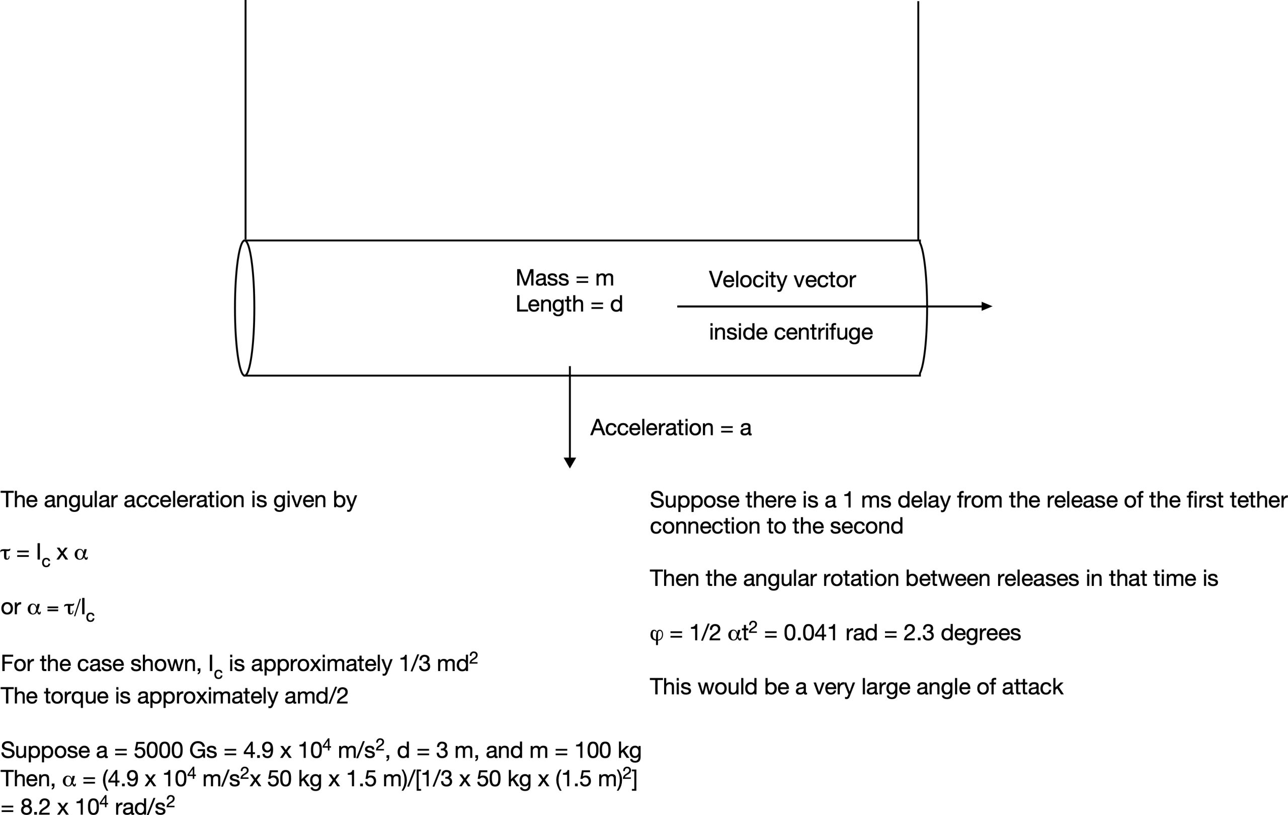 Figure 1. Estimation of angle of attack induced by lack of simultaneity in two-point release mechanism
This calculation shows that at the fairly modest centripetal acceleration of 5000 Gs, an angle of attack of about 2.3 degrees would be induced with a delay of only 1 ms between release of the two points. Such an angle of attack could have substantial detrimental effect on vehicle performance.
Thoughts and Observations on SpinLaunch
SpinLaunch has done an amazing job of designing, constructing, and putting into service their suborbital centrifugal accelerator. The launcher is a complex and massive system whose fabrication, assembly, and operation to date have taken place in an environment that is quite isolated and not even served with commercial electric power. A further complication was that site preparation work, fabrication of the centrifuge, and other key program elements were in their early stages just as the COVID lock-downs were being imposed.
The company already had extensive experience with a much smaller accelerator that had been in service for a number of years in California, but everything about the accelerator at Spaceport America dwarfs the earlier installation. Numerous aspects of the project represent largest-best-first ever technological accomplishments. Some of the more interesting details are:
-
-
-
- The vacuum chamber is roughly 106 ft in diameter and 25 ft thick. It weighs approximately 2.5-million pound.
- Most parts of the vacuum chamber are 3 inches thick, but it is up to 6 inches thick in critical areas.
- The steel sides of the vacuum chamber fit together like petals of a daisy. They were fabricated off-site and welded together at Spaceport America.
- The centrifuge was fabricated in a horizontal orientation a few hundred feet from the support pedestal that was fabricated separately. A firm that specializes in moving huge objects was engaged to raise, transport, and install it n the pedestal.
- The total weight of the centrifuge including the support structure is about 3.5 million pounds.
- Aside from the engineering talent required to design the system, advanced welding skills were probably the most important skill-set required to compete the project.
- At the height of construction, well over 100 personnel were actively engaged in fabrication.
- Very large vacuum pumping capacity is required to evacuate the centrifuge.
- During operations, multi-megawatts of electrical power are required to power the vacuum pumps and the drive system of the centrifuge.
- The operational facility includes a dirt airstrip so that key individuals who must divide their time can be efficiently transported into and out of the site.
-
-
Tens of millions of dollars have been spent in New Mexico and numerous commercial and government organizations are aware of what New Mexico has to offer as a result of the SpinLaunch project.